CAN bus layout, structure and basic features
CAN bus layout, structure and basic features
There are multiple originals connected in parallel on the CAN bus system, which requires the entire system to meet the following requirements:
1. High reliability: transmission failure (whether caused by internal or external) should be accurately identified;
2, easy to use: If a control unit fails, the rest of the system should maintain the original function as much as possible while exchanging information;
3. The data density is large: the information state of all control courtyards is the same at any instant, so that there is no data deviation between the two control units. If there is a fault in one part of the system, all connected originals on the bus will be notified.
4, data transmission fast: the data exchange rate between the components of the network must be very fast, in order to meet the real-time requirements.
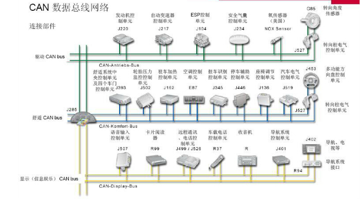
Considering the repetition rate of the signal and the amount of data generated, the CAN bus system is divided into three specialized systems:
1, CAN drive bus (high speed), 500Kbit / m, can basically meet the real-time requirements;
2, CAN comfort bus (low speed), 100Kbit / m, used for time requirements are not high;
3, CAN "infotainment" bus, (low speed), 100Kbit / m, used for time requirements are not high.
The CANBUS system assembly part includes the CAN transceiver, the data transmission terminal, and the data transmission line. The CAN transceiver is installed inside the controller. The colleague has both the function of receiving and transmitting, and the data transmitted from the controller is converted into an electrical signal and sent. The data transmission line is a resistor that prevents the data from being reflected at the line end and returns in the form of echo, which affects the transmission of data. The data transmission line uses a two-wire data line and is composed of high and low twisted pairs.

